Fixing 3D Printings Weak Spot with Curved Layers
If you’ve ever snapped a 3D printed part, you probably noticed something suspicious: it didn’t break randomly. It broke cleanly along a layer line, like a piece of shale splitting along its sediment layers. That’s not bad luck — it’s baked into how FDM printers work. And there’s a fix quietly making its way from research labs into open-source slicers: printing in curved layers instead of flat ones.
A stack of welds, not a solid part
A fused deposition modeling (FDM) printer builds objects by extruding molten plastic in flat, horizontal layers, one on top of another. Within a layer, the plastic is a continuous extruded bead — strong stuff. But between layers, you’re relying on a thermal weld: the fresh, hot layer has to partially re-melt the surface of the layer below, which has already cooled, so the polymer chains can diffuse across the boundary. That weld is never as good as the bulk material.
The result is anisotropy — the part’s strength depends on which direction you pull it. Industry testing consistently shows that Z-axis tensile strength can be 30–50% lower than in-plane strength, and one Formlabs comparison measured Z-axis yield strength at roughly 55% of the X-axis value for an FDM part. Ductility suffers even more: the Z direction may retain only 10–30% of the elongation you’d get pulling along the layers. Every layer boundary is a plane of weakness, all of them perfectly parallel, all of them aligned. When the part fails, that’s where it lets go — which is exactly why your prints always snap along the same lines.
There’s a second, more visible symptom of flat layers: the staircase effect. Any surface that slopes gently relative to the build plate gets approximated by a series of steps, like contour lines on a topographic map. It looks bad, it traps stress concentrations, and thinner layers only shrink the stairs — they never eliminate them.
Bending the layers
The core idea behind non-planar (or “curved-layer”) FDM is simple: if the part’s surface is curved, why should the layers be flat? A standard 3-axis printer can already move its nozzle in X, Y, and Z simultaneously — mesh bed leveling has exploited this for years. Non-planar slicing takes it further and generates toolpaths where the nozzle rises and falls within a layer, laying down beads that drape over the geometry like fabric instead of stacking like plywood.
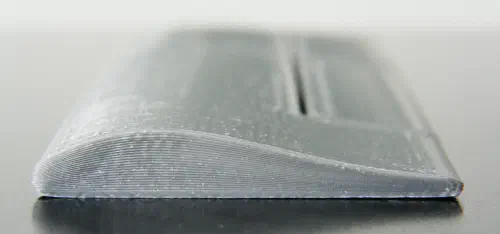
This does two useful things at once. First, surfaces come out smooth: a shallow dome or wing profile printed with conformal top layers has no staircase at all, because the layers follow the surface instead of sampling it. An early hands-on exploration on Hackaday demonstrated near-Class-A surfaces straight off the printer, no sanding required.
Second, it changes the mechanics of the layer interfaces. When layers are flat and a tensile load pulls perpendicular to them, the weld carries pure tension — its weakest mode. Curve or corrugate the interface and part of that load converts into shear along the interlocking surfaces, which FDM welds handle much better. Recent research backs up the strength story: a study in Processes on filament orientation strategies for non-planar printing found better structural integrity and surface uniformity on inclined geometries (with a ~30° filament orientation working best), and work published in 2025 on optimizing non-planar FDM reports gains in both surface quality and mechanical performance from adaptive, hybrid layer strategies. A short review of curved-layer FDM reaches the same broad conclusion: strength and surface finish both benefit.
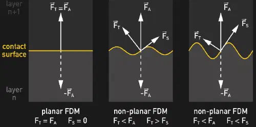
One honest caveat: the picture isn’t unanimous. In early independent testing, the developer of one experimental non-planar slicer found that pure Z-tension strength barely changed with layer curvature, because a tilted nozzle compresses the bead less effectively. The clearer wins are in shear-loaded and bending scenarios, in eliminating the stress-concentrating staircase notches, and in how the geometry distributes load — a review of mechanical properties across non-planar strategies shows the benefit depends heavily on the specific technique and load case. “Curved layers” is a family of tricks, not one magic setting.
From SIGGRAPH paper to slicer checkbox
For a long time this was robot-arm and five-axis territory. The interesting shift is that it now runs on ordinary Cartesian printers. The landmark CurviSlicer project (SIGGRAPH 2019, from Inria) showed a clever route: instead of computing curved paths directly, it optimizes a deformation of the model, slices the deformed version with boring flat planes, then un-deforms the toolpaths — out come curved layers, throughout the whole part, on a stock 3-axis machine. Around the same time, Daniel Ahlers at the University of Hamburg built an open-source Slic3r fork that automatically detects which surfaces benefit from non-planar layers and generates collision-free paths using a geometric model of the print head.
That collision bit is the real engineering constraint. Your nozzle isn’t a point — it’s attached to a hot, blunt assembly, and when it dives into a valley of the print, the surrounding hardware can crash into already-printed peaks. Practical non-planar printing favors pointy nozzles, limited slope angles, and hybrid strategies: flat layers for the bulk interior, curved layers where they matter. A recent non-planar slicer algorithm formalizes exactly this mixed approach, carving the curved-layer regions out of the mesh so the rest can be sliced conventionally, and researchers have even adapted PrusaSlicer’s pipeline for curved-layer printing.
The hobbyist side is moving fast too. In 2025, Joshua Bird’s experimental S4 Slicer — which computes curved layer fields over a tetrahedral mesh of the model — made the rounds, with demos of dramatically non-planar prints on lightly modified consumer hardware. None of this is a mainstream slicer checkbox yet, but the trajectory looks a lot like mesh bed leveling a decade ago: exotic hack first, firmware feature later.
If your prints keep snapping along the same line, the short-term fixes are still the classics — reorient the part, run the chamber hotter, add perimeters. But the long-term fix is more satisfying: stop printing plywood, start printing something closer to grain-following wood.
References
- https://www.researchgate.net/publication/332960110_CurviSlicer_Slightly_curved_slicing_for_3-axis_printers
- https://cims.nyu.edu/gcl/papers/2019-CurviSlicer.pdf
- https://3dprintingindustry.com/news/smooth-operation-eliminates-fdm-stair-stepping-in-university-of-hamburg-study-160826/
- https://dl.acm.org/doi/10.1109/COASE.2019.8843116
- https://dl.acm.org/doi/abs/10.1145/3550454.3555516
- https://arxiv.org/pdf/2408.04827
- https://www.inria.fr/en/fully-round-3d-printing
- https://3dspro.com/resources/3dspro-lab/3d-printing-designs-impact-on-mechanical-properties-anisotropy